Autonomous CO Detection Robot
Orchestrated Autonomy for Hazardous Environments
Virginia Tech Senior Design Team 44 | April 2024

Labeled physical prototype of the autonomous robot.
Objective
To advance the concept of Orchestrated Autonomy through the development of a low cost, functional robot prototype designed for autonomous movement and toxic gas detection to reduce human exposure in hazardous environments.
Project Highlights
A* Path Planning
Successfully implemented the A* algorithm for efficient, grid-based pathfinding, as demonstrated in live testing.
Dynamic Obstacle Detection
Utilized LiDAR to detect unknown obstacles and dynamically recalculate navigation routes in real-time.
UDP Communication Protocol
Established a robust UDP protocol for wireless data exchange and fleet coordination with a central server.
Budgetary Efficiency
Delivered the project 22% under the $5,000 budget, demonstrating cost-effective resource management.

Chassis & Drive
6061-T6 aluminum frame with custom hex shafts and PID-controlled skid-steer drive system.
Power & Compute

Distributed architecture: Arduino Giga R1 (motor control/comms) + Arduino Mega (LiDAR processing).

Dual 12V LiPo batteries in parallel with regulated 5V rails for >30 min runtime.

Sensor Coverage
360° LiDAR object detection with grid-based movement and CO concentration mapping.

Multi-tiered software architecture for robot prototype
Control Loop

Sequence diagram for control loop
Autonomous Operation
The robot operates as a client on a wireless network. It receives a map and goal coordinates from a central server, calculates the optimal path using the A* algorithm, and executes movements while continuously monitoring its environment.
Dynamic Response
If the LiDAR sensor detects an unknown obstacle (not in the current provided map), the robot halts immediately, updates its local map, recalculates a new path around the obstacle, and reports the discovery to the central server so other robots in the fleet can avoid it.
UDP Fleet Communication

UDP client-server protocol for fleet coordination between path planning laptop and robot.
Key Software Components I Developed
- •A* Path Planning: Grid-based pathfinding with real-time recalculation when obstacles are detected
- •LiDAR Processing: Forward-facing scan data processing with 3-search-area method for obstacle detection in the target grid space
- •UDP Communication: Client-server protocol for fleet coordination and real-time status reporting
1. Path Following Demonstration
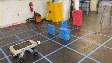
The robot receives a map and goal coordinates, calculates the optimal path using A*, and executes precise grid-based movements to reach the destination.
2. Simple Obstacle Detection & Update

A* Path Recalculation


When the robot encounters an unknown obstacle (red), it halts, adds the obstacle to its map, and recalculates a new path. This process repeats until the goal is reached.
3. Advanced Maze Scenario
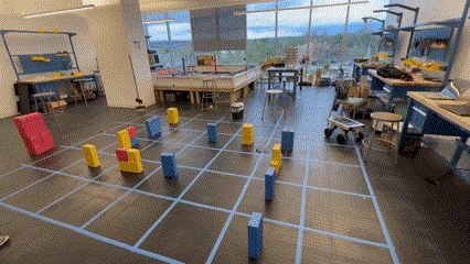
A more complex scenario with multiple unknown obstacles forming a maze-like environment. The robot must repeatedly detect, update, and renavigate to find a viable path to the goal.
Software Requirements
Core software capabilities required for orchestrated autonomy integration. Each requirement is binary—the system either achieves the capability or it does not.
| ID | Requirement | Description | Status |
|---|---|---|---|
| SW-01 | Path Planning | Calculate optimal path using A* algorithm in grid-based environment | ✓ Pass |
| SW-02 | Obstacle Detection | Detect unknown obstacles via LiDAR and halt before collision | ✓ Pass |
| SW-03 | Dynamic Renavigation | Recalculate path when obstacles block current route | ✓ Pass |
| SW-04 | Fleet Communication | Real-time UDP data exchange with central server | ✓ Pass |
| SW-05 | CO Detection | Detect and report carbon monoxide concentration (ppm) | ✓ Pass |
| SW-06 | Status Reporting | Generate accurate status messages for fleet integration | ✓ Pass |
| SW-07 | JSON Message Format | Structured JSON formatting for inter-system communication | △ Partial |
Note: SW-07 used simple text command lists instead of JSON; functional but less structured than spec.
Hardware Requirements
Physical performance requirements for field deployment in hazardous environments.
| ID | Requirement | Target | Actual | Status |
|---|---|---|---|---|
| HW-01 | Battery Life | ≥30 min continuous operation | >30 min (12.2V after 30 min) | ✓ Pass |
| HW-02 | Top Speed | ≥1 m/s | ~0.7 m/s | △ Partial |
| HW-03 | Terrain: Grass | Navigate grass surfaces | Validated | ✓ Pass |
| HW-04 | Terrain: Gradient | ≥5% gradient | Up to 12% tested | ✓ Pass |
| HW-05 | Ground Clearance | ≥2" curb clearance | 2" curbs cleared | ✓ Pass |
| HW-06 | Motor Torque | Stay under nominal torque | Peak 9.07 kgf·cm (under limit) | ✓ Pass |
Note: HW-02 (Top Speed) was impacted by a supply chain issue that forced a substitution to lower-RPM motors.
Validation Methodology
A* Algorithm Validation
- • Boundary condition testing (map perimeter, no-path scenarios)
- • Mathematical correctness checks on hardcoded maps
- • Real-world path execution with encoder feedback
Integration Testing
- • Unknown obstacle placement during navigation
- • Multi-obstacle maze scenarios
- • Error message generation and handling
Communication Protocol
- • UDP packet transmission/receipt verification
- • Command execution confirmation loop
- • CO reading and obstacle status reporting
Hardware Validation
- • Battery life: 30+ min continuous operation
- • Motor torque limits on varied terrain
- • LiDAR 3-search-area obstacle detection
A* Algorithm Verification
The path planning algorithm was validated through mathematical verification and systematic edge case testing before real-world deployment.
Mathematical Validation
- • Verified optimal path output against hand-calculated solutions
- • Confirmed correct traversal cost calculations (movement + heuristic)
- • Validated node selection order follows A* priority
Edge Cases Tested
- • Start/goal on map boundary
- • No viable path exists (blocked goal)
- • Start equals goal position
- • Single-path corridors and chokepoints
Dynamic Scenarios
- • Mid-path obstacle insertion triggers recalculation
- • Multiple sequential obstacles (maze navigation)
- • Path blocked after partial traversal
Error Handling
- • Graceful failure when no path found
- • Correct status messages returned to base station
- • Robot halts safely on unrecoverable errors
Tradeoffs & Constraints
Sensor Coverage
LiDAR detection was limited to objects directly in front of the robot within the 3-search-area range. Objects behind or to the sides were not monitored during forward movement.
Wireless Range
The operational range from base station to robot was not explicitly measured. Theoretical range depends on the Wi-Fi signal strength of the base station/server hotspot.
Battery Capacity
The 30+ minute runtime, while meeting requirements, is limited for practical field deployment. Higher-capacity batteries or more efficient power management would extend operational time.
Failures & Lessons Learned
Hex Shaft Fatigue Failure
Two custom hex shafts underwent brittle fatigue failure due to large stress concentration factors where the different-size hexes met.
Recommendation: Design a tapered shaft to reduce stress concentration and/or use a material with higher fatigue strength (e.g., steel) which possesses a fatigue limit.
Lesson: Fatigue fracture design is just as important as designing for yield, especially in rotating parts which undergo stress cycles.
Electrical Noise Interference
Due to space restrictions, power wires produced electrical noise that disrupted motor control and IMU positioning signals. This caused significant testing setbacks before being resolved.
Recommendation: Reorganize the electrical circuit, eliminate the breadboard, and solder wires directly to a PCB to reduce noise and prevent vibration-induced disconnections.
Impact & Significance
Orchestrated Autonomy Integration
Noblis' orchestrated autonomy concept requires robots to operate independently while seamlessly integrating with a coordinated fleet. This means each unit must:
- • Receive mission parameters (map, goal) from a central server
- • Execute tasks autonomously without continuous human control
- • Report discoveries (obstacles, sensor data) back to the fleet in real-time
- • Respond to dynamic updates as other robots share information
Our system validated all four capabilities. The robot successfully received maps via UDP, navigated autonomously using A*, reported unknown obstacles to the server, and could theoretically respond to fleet-shared map updates—proving the core integration pattern works.
Impact of Partial Requirements
Top Speed (0.7 m/s vs 1 m/s target)
In hazardous environment deployment, slower speed means longer area coverage time—critical when battery life is limited and human safety depends on rapid assessment. However, for proof-of-concept validation, the 30% speed reduction doesn't affect the core autonomy demonstration. The fix (higher-RPM motors) is a straightforward hardware swap.
JSON Message Format (text commands used instead)
Simple text commands worked for single-robot testing but would limit scalability in a multi-robot fleet where structured data exchange enables richer coordination. Migration to JSON is a software update with no hardware changes required.
Bottom Line
The prototype successfully proved that a low-cost autonomous robot can integrate with Noblis' orchestrated autonomy framework. All software requirements for fleet integration were met, and the partial hardware requirements have clear, implementable solutions. The system exceeded sponsor expectations and demonstrates a viable path toward scalable hazardous-environment deployment.
Team Members
Mechanical Design
- Nathan Carpenter — Project lead, CAD design, chassis design & validation
- Joshua Menezes — Motors, chassis design & validation, battery systems
- Mohamed Eldirdiri — CO sensor integration
- Wang Geun Lee — Tires, CO sensor integration, documentation
Software Design
- Taylor Pippen — A* path planning, LiDAR processing, UDP protocol
- Sam Wood — PID control, mechatronics, electrical systems, battery systems
- Joshua Menezes — UDP protocol support
Faculty Advisor
Dr. Kaveh Akbari Hamed
Sponsor
Noblis — Orchestrated Autonomy Research Division
Key Contacts: Andrew Dudash, Mohammad Goli
Presented at the 2024 Virginia Tech Mechanical Engineering Senior Capstone Exposition